
Triggered Oscilloscope over UDP
Noisy waves on my computer screen
(The ADCs onboard this board can be rather noisy. I'm still looking for improvements...)
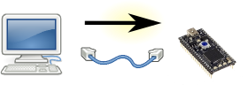
Step 1: the PC sends a "Triggered Oscilloscope Command" to the mbed.
(eg: "Please trigger at 1.1 V, rising.")
Step 2: the mbed immediately sends back a "Triggered Oscilloscope Metadata" packet,
which describes the timebase, and the voltage ranges of each of the channels.
(typically one, single packet. eg: "1 ms per div, 1 V per div")
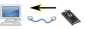
Step 3: when the trigger condition is met, the mbed sends the actual data to the PC
(typically several packets)
Step 4: the PC draws the graph on the screen. When the PC is ready, it returns to step 1.
The circuit for this demo:
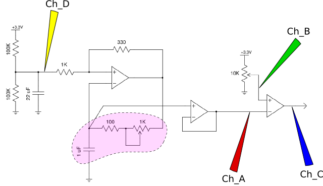
PWM with 4 probe points. Purple area is the RC circuit.
op amp: The op amp that I used was the LM324 (quad op amp from National Semiconductor). Vcc = 3.3 V
RC oscillator: The purple area is the RC circuit. Frequency range is ~200 Hz to ~1800 Hz.
Channel A, red: the (sort-of) sawtooth wave from the oscillator
Channel B, green: user set the PWM duty cycle
Channel C, blue: PWM output
Channel D, yellow: this is the average voltage on the first op amp
Here is an example screen from this circuit:
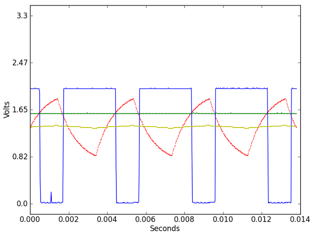
Blue Trace: PWM at 250 Hz, 70% duty cycle
Note that the red,green,blue traces are a comparator (an op amp with open gain). Whenever the green is higher than the red, the blue goes to max. Conversely, whenever the green is lower than the red, the blue goes to min.